Presentation of my astrophoto plateform
This page presents my platform to make astronomical photos
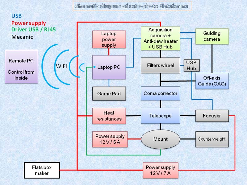
Most hardware components are shown in the schematic diagram below and are also described in the "Equipment" part of this website.
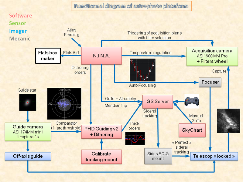
The various software used by this platform dedicated "astrophoto" are shown in the schematic diagram hereafter.
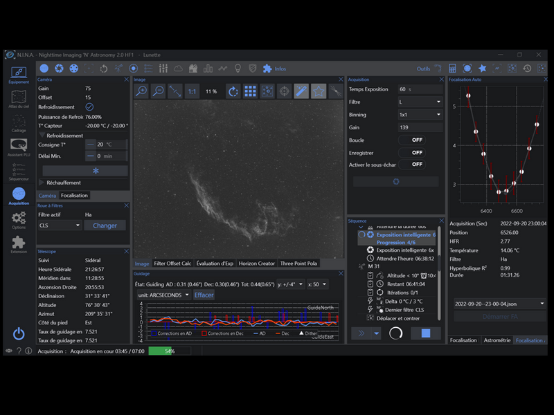
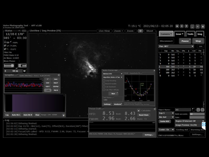
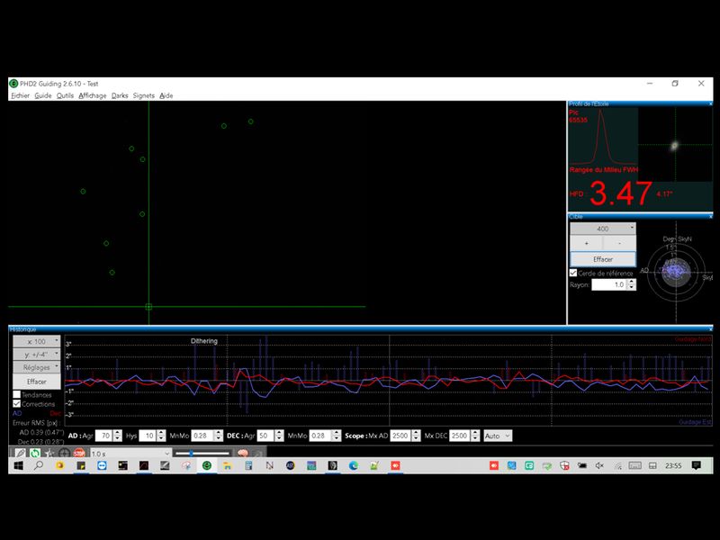
Finally, an example of acquisition session is proposed at the end of this page via a desktop screenshot that can see the software interfaces.
Description of the schematic diagram of astrophoto plateform :
This scheme brings up the types of connections between the components in a different color : power supply (12V), USB cables, USB cables "driver" for interfacing with other equipments and mechanical assembly.
It also appears, in a different color, the types of materials used : Electrical, mechanical, imagers, correctors / filters and CCD sensors.
It is therefore the laptop PC which controls, thanks to several software applications, all the electronic equipments : the mount, the acquisition camera with the guiding camera, the filter wheel, the focuser and the joystick
The display of the laptop PC (that is located in the garden) is deported via the WiFi network to a PC located inside the house from where the platform can be fully controlled (ideal when it's cold or for avoid mosquitoes)
Description of the functional diagram of astrophoto plateform :
This diagram shows the general operation of the plateform that allows long exposures on an object that remains fixed in the imaging field through a servo based on a guidance system.
The mount is aligned on the polar star and with the sidereal tracking mode switch on, controlled by the "GS Server" application (EQMOD like) which can receive movement orders from all compatible applications (Example: APT, PHD Guiding, SkyChart, Joystick, ...). However, this monitoring is noisy, essentially with games gears and mechanical bending of the whole assembly. The consequence of this noisy tracking is that the object moves around a mean value, and will therefore be blurred on a picture taken with a long exposure time (> 30 s)
To remedy this, we must set up a servo that will be able to reset periodically the object to its original position (shifting). The system used here is based on an optical divider or "off-axis guide" that will capture at a rate of 1 frame/s a a guide star close to the object to be imaged using a monochrome camera. The control is realized with the PHD Guiding V2 software that compare the current image of the guide star to the previous one and send, if necessary and according to a predefined threshold, orders in RA / DEC to the mount in order to reset the telescope on the initial position (before starting the homing, PHD2 has to model the "gross" tracking of the mount by calculating the RA and DEC vectors and the DEC game)
The sharpness of the long exposure imaged object will strongly depend on the quality of guidance (good sampling, proper adjustment of the thresholds) but also on other factors such as the level of atmospheric turbulence and the wind. Noted that recent versions of PHD2 allow changing the guide star if the one that was initially chosen is no longer sufficiently visible
The long exposure control is done from APT software tha allow the dithering mode with PHD2 : the dithering corresponds to a movement of a few pixels via an order to the mount that reduces noise frames that are identical between each image during the stacking phase pretreatment. The guidance commands sent by PHD2 are filtered through the "Pulse guide" mode of the GS Server software interface that allows a softer guidance.
The change of an object is done automatically with APT software which allows the programming of acquisition plans (with the use of numerous scripted commands) which are themselves called by the control session. Acquisitions are triggered or stopped depending on different events (taking into account the reversal of meridian, need to redo an automatic focus, time or end of night condition reached, ...)
In addition, the APT application allows you to perform an intelligent GoTo (GoTo++) in order to center perfectly (after several iterations) an planned object from a capture that follows the GoTo and comparing it with a stars catalog. The focus is also managed automatically (Auto-Focus Aid) thanks to an algorithm based on the HFD of the stars present in the successive captures in order to choose the position of the focuser which corresponds at the smallest HFD value estimated from the parabola.
The creation of "Flat field" calibration images is also well assisted by APT (CCD Flats Aid) which can drive a Lacerta brand flat screen for example and define the exposure time corresponding to the chosen ADU value then launch the creation of the series by programmed filters
Example of acquisition session controlled by N.I.N.A. or APT applications :
This following screenshot shows the different human-machine interfaces (HMI) used to monitor the guidance, the long exposures control, the focus quality, the temperature regulation of the acquisition camera and the estimated time
The interface corresponding to the "PHD Guiding V2" guidance software follow-up the corrections sent to the mount with a target showing the various position errors of the tracked object from the initial position (center target). The tracking quality criterion is customizable but if you want a good track, it is best to have all the "impacts" in a target set to maximum 2.5" arc (for information, we can never drop below the 1" arc threshold because it corresponds approximately to the disturbance of air turbulence from the CCD sensor and the tracking would be continually locked on turbulence !)
This example shows that the corrections are substantially on the RA axis: if the frame was perfectly aligned with the Earth's rotation axis, corrections on the DEC axis would be null and therefore the best guidance quality you would have !) A little trick that allows better guidance on the RA axis is not to perfectly balance the payload on this mount axis: in order not to try to catch the game of the worm constantly, it is better to have the cog-wheel always support to the payload side for West tracking and vice versa for an East tracking (imbalance in favor of the payload and not to the counterweight side for a West tracking) However, if objects are programmed both before and after the meridian, it is necessary to balance the load of the frame as well as possible
Example of acquisition plan session from N.I.N.A. application with tracking and focus monitoring
Example of acquisition plan session from APT application with tracking and focus monitoring
Example of PHD2 monitoring with guiding star target and dithering orders sent to GS Server
GS Server application that control sideral track of the mount and received track orders
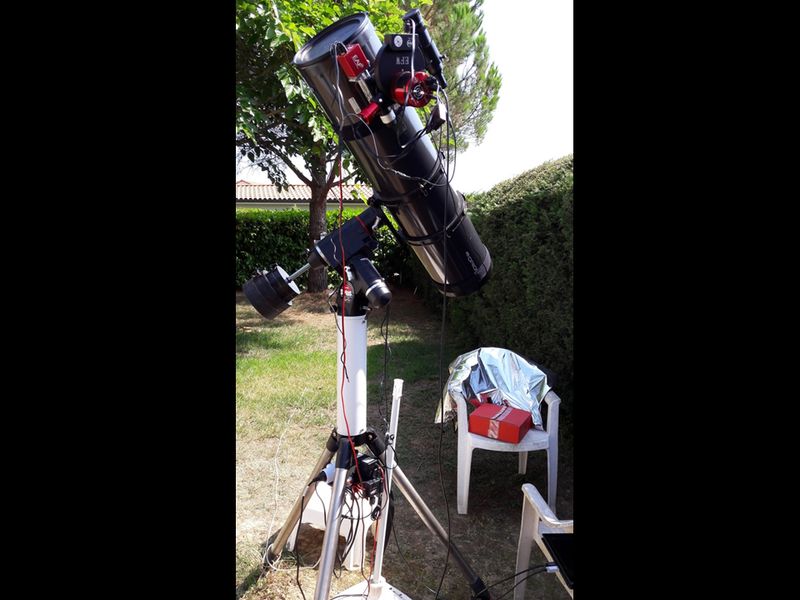
My hardware plafeform

